
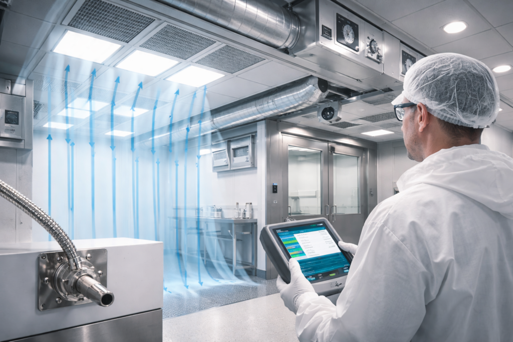
In the high-stakes environments of pharmaceutical manufacturing, semiconductor fabrication, and aerospace engineering, the air is not merely a medium for temperature control—it is a tightly regulated variable. The ISO 14644-1 standard serves as the international primary directive for classifying air cleanliness by particle concentration. For mechanical engineers and technical offices, designing a system that meets these rigorous benchmarks requires a departure from standard HVAC logic, shifting the focus toward microscopic filtration efficiency and highly controlled fluid dynamics. Achieving compliance is not a one-time event but a continuous engineering challenge that begins at the initial design phase and extends through the entire life cycle of the facility.
The Mathematical Framework of Particle Concentration and Classification
The fundamental principle of ISO 14644-1 revolves around the maximum permitted concentration of particles per cubic meter of air (Cn). The standard covers a spectrum of particle sizes, typically ranging from 0.1 um to 5.0 um. As the ISO Class number decreases (e.g., from ISO 8 to ISO 5), the allowable particle count drops exponentially. For instance, an ISO Class 5 environment—often used in sterile filling—permits no more than 3,520 particles per m³ at the 0.5 um threshold.
From an engineering perspective, this classification dictates the entire mechanical architecture. While a standard office space might focus on occupant comfort, a cleanroom focuses on “sweeping” particles away from critical surfaces. This is achieved through the integration of High-Efficiency Particulate Air (HEPA) or Ultra-Low Penetration Air (ULPA) filters. When we evaluate services in specialized ventilation, we emphasize that the filtration strategy must be supported by air change rates (ACR) that often exceed 20 to 60 changes per hour, depending on the targeted ISO class.
In a typical field scenario, a technical office might be tasked with designing a cleanroom for an electronics assembly line. A common pitfall occurs during the “At-Rest” versus “Operational” state classification. A room may easily meet ISO Class 6 requirements when empty, but the moment personnel enter and equipment begins to move, particle generation spikes. Without a robust “Recovery Rate” calculation—measuring how quickly the system can return to its baseline cleanliness—the facility risks non-compliance during critical production cycles.
Airflow Patterns: Unidirectional vs. Non-Unidirectional Design
The mechanism by which clean air is introduced into the space is just as critical as the filtration itself. ISO 14644-1 implicitly distinguishes between two primary airflow regimes: Unidirectional (Laminar) and Non-Unidirectional (Turbulent).
- Unidirectional Flow: Primarily utilized in ISO Class 5 and cleaner environments. Air moves in parallel streams, typically from the ceiling toward a perforated floor, at a constant velocity (usually between 0.36 to 0.54 m/s). This “piston-like” effect minimizes air turbulence and prevents particle re-entrainment.
- Non-Unidirectional Flow: Common in ISO Class 6 to 9. Clean air is introduced through ceiling diffusers and mixed with room air to dilute contaminants.
The engineering logic here is centered on the “Dead Zone” avoidance. If a mechanical installation does not account for the placement of large machinery, stagnant air pockets can form where particles accumulate. In our about us detailed engineering vision, we prioritize the synergy between 3D modeling and airflow simulation to identify these risks before ductwork is ever fabricated.
A frequent field error involves the improper balancing of return air grilles. In a Turkish pharmaceutical project recently analyzed, the air was short-circuiting because return grilles were placed too high on the walls, leaving a “dust blanket” near the floor level where the actual product was exposed. Correcting this required a redesign of the low-level return plenum to ensure a true top-down sweep of the environment.
Pressure Differentials and Environmental Integrity
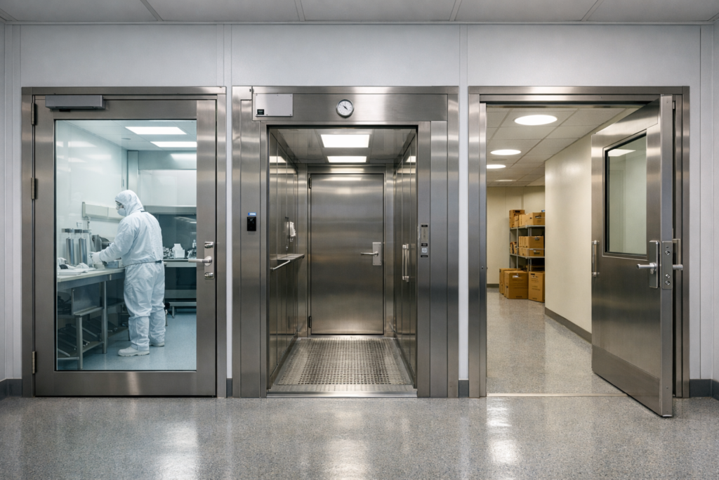
A cleanroom does not exist in a vacuum; it is part of a larger building ecosystem. To maintain the integrity of a classified space, mechanical engineers must design a “Pressure Cascade.” This involves maintaining a positive pressure (typically +10 to +15 Pascals) relative to adjacent, less-clean areas. This pressure gradient ensures that when a door is opened, air flows out of the cleanroom, preventing unfiltered air from “leaking” in.
Technical office teams must meticulously calculate the leakage rates of the room envelope—including gaskets, door seals, and cable penetrations. If the room is not sufficiently airtight, the AHU (Air Handling Unit) must increase its fan speed to maintain the pressure setpoint, leading to excessive energy consumption and potential filter bypass. Detailed analyses of these energy-efficient mechanical designs are a frequent topic in our blog section, where we explore the intersection of cleanroom standards and operational costs.
Critical Engineering Warnings:
- Filter Face Velocity: Ensure that the velocity across the HEPA filter face is uniform. Non-uniformity can cause localized turbulence, breaking the “laminar” seal.
- Differential Pressure Sensor Placement: Sensors should be placed away from high-velocity air streams or door openings to avoid erratic readings that can trigger false alarms in the Building Management System (BMS).
- Material Compatibility: Standard galvanized ductwork may not be sufficient for cleanrooms requiring frequent chemical VHP (Vaporized Hydrogen Peroxide) decontamination. Stainless steel or specialized coatings are often required to prevent corrosion.
Commissioning, Validation, and the E-E-A-T Approach to Maintenance
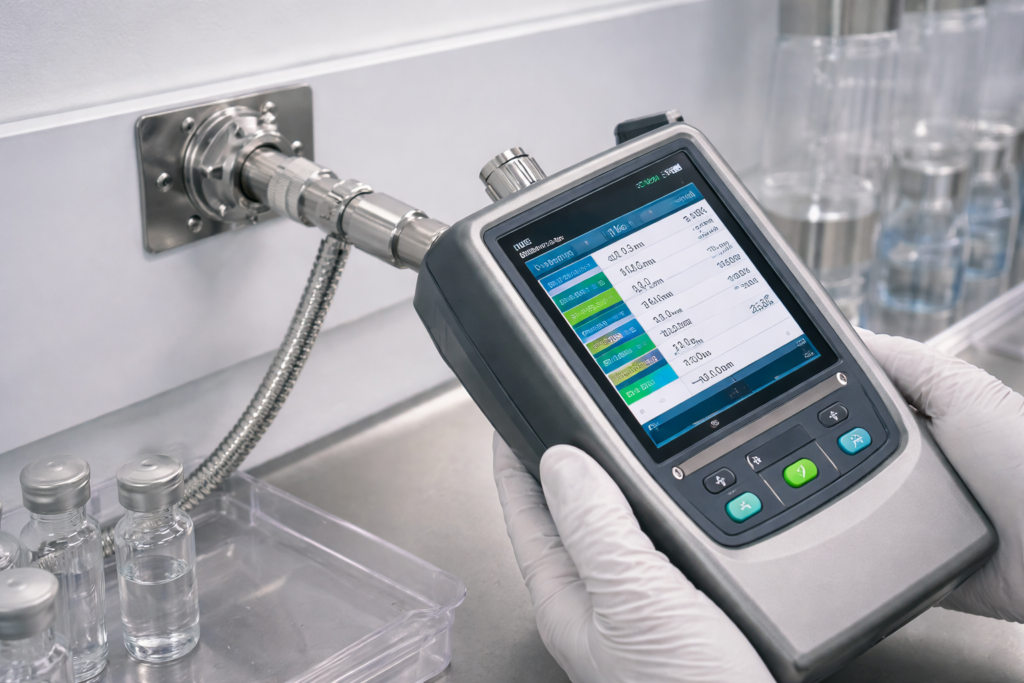
Final certification of an ISO 14644-1 environment is a rigorous process involving particle counting, airflow velocity testing, and filter integrity (DOP) testing. In Turkey, adherence to these standards must also align with local health and safety regulations, particularly in medical grade facilities. A “passed” test at handover is only the beginning; the engineering team must provide a robust maintenance protocol.
Cleanroom Validation Checklist:
- Particle Count Test: Conducted at “At-Rest” and “Operational” states across a grid of sampling points.
- Airflow Velocity: Verification of unidirectional flow speeds to ensure they fall within the 0.45 m/s ±20% range.
- Pressure Gradient: Confirmation that all airlocks and pass-throughs maintain the designed Pascal differential.
- Leakage Test: Integrity testing of HEPA filter seals using aerosol photometers.
A common scenario we encounter in the field involves the degradation of HEPA filters due to lack of pre-filtration. If the G4 or F7 pre-filters in the AHU are not changed on schedule, the expensive HEPA filters will clog prematurely, causing a catastrophic drop in airflow and room pressure. This highlights the importance of a coordinated MEP approach where purchasing and technical office teams work in sync. For complex facility upgrades or new cleanroom projelendirme, our technical office is available for a detailed get a quote regarding specification and equipment selection.
The ultimate goal of ISO 14644-1 compliance is risk mitigation. Whether it is preventing a batch of pharmaceuticals from being contaminated or ensuring a microchip functions correctly, the ventilation system is the first line of defense. For further technical consultation or specialized equipment specifications, our engineering team is ready to assist through our contact channels.