
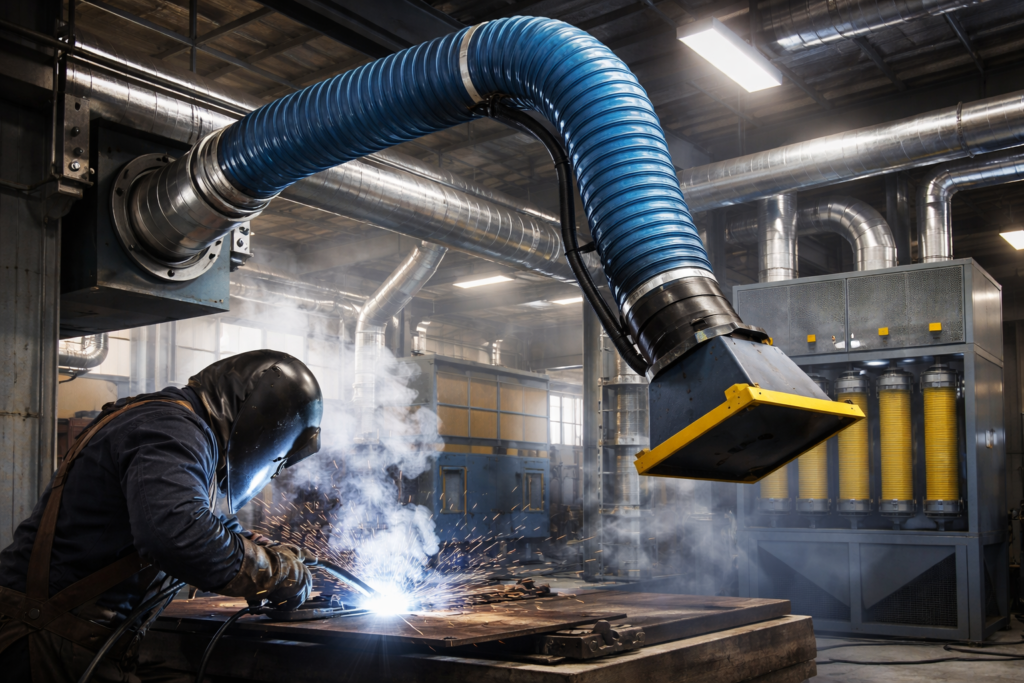
In industrial environments, managing airborne contaminants is not just a matter of air quality—it is a critical safety and compliance mandate. Unlike general dilution ventilation, which mixes fresh air with polluted air, Local Exhaust Ventilation (LEV) is designed to capture dust, fumes, vapors, and gases right at the point of origin before they reach the worker’s breathing zone. For technical offices and mechanical engineers, designing an LEV system is an exercise in fluid dynamics and source control. At AVENT PROJE, our services focus on creating high-efficiency extraction systems that protect both personnel and sensitive machinery from the abrasive or toxic effects of industrial byproducts.
The Engineering Logic of Capture Velocity and Hood Design
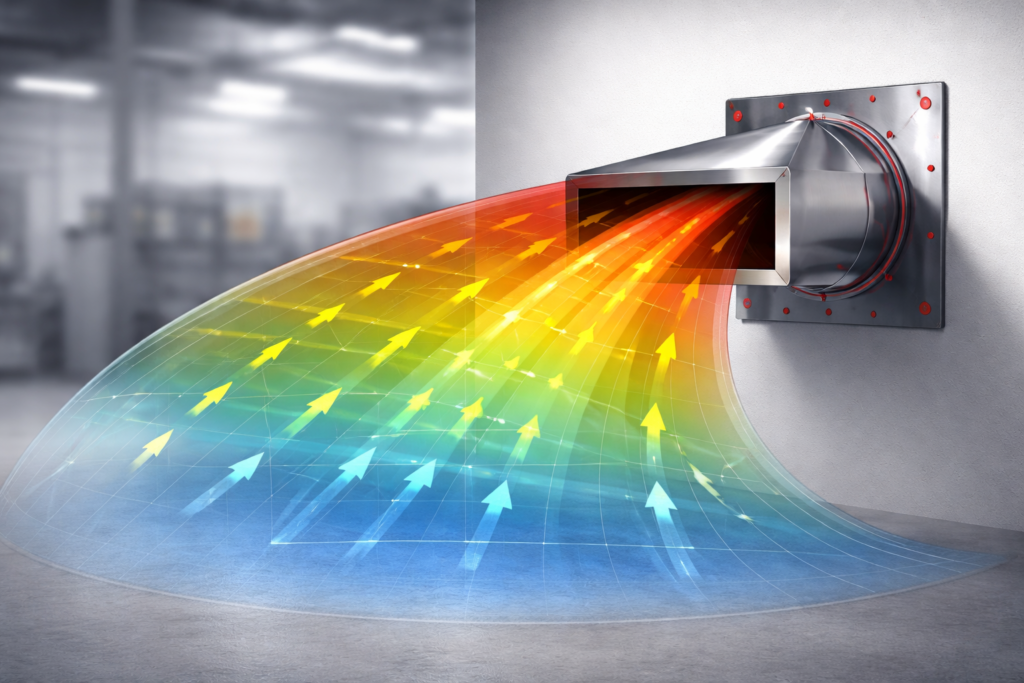
The most vital component of any LEV system is the “hood” or inlet. The effectiveness of the entire system depends on its ability to create a sufficient Capture Velocity—the air speed required to overcome the motion of the contaminant and pull it into the ductwork. If the capture velocity is insufficient, the hazardous particles will escape into the workshop, rendering the system useless regardless of how powerful the fan is.
The relationship between airflow and distance from the source is governed by the principle that air velocity drops off rapidly as you move away from the hood opening. A common engineering formula used to estimate required airflow for an open hood is: Q = V × (10X² + A), where V is the required capture velocity, X is the distance from the source, and A is the area of the hood opening.
In a typical field scenario, such as a welding station, we often see hoods placed too far from the work area. A welder might move the hood 20 cm away for better visibility, but because the airflow requirement increases with the square of the distance, that small move might require a fourfold increase in fan power to maintain capture. Our about us highlighted engineering vision focuses on designing “Enclosing” or “Receiving” hoods whenever possible, as they require significantly less air volume to achieve 100% containment compared to “Reach-in” hoods.
Transport Velocity: Ensuring Contaminants Reach the Filter
Once the contaminant is captured, the LEV system must move it through the ductwork to the filtration unit. This requires maintaining a specific Transport Velocity (or conveying velocity). If the air moves too slowly, heavy dust particles or condensed vapors will settle in the ducts, leading to blockages, fire hazards, or increased static pressure.
Different materials require different minimum transport velocities:
- Gases and Vapors: 1,000 – 1,200 FPM (5 – 6 m/s)
- Fine Wood Dust: 3,500 – 4,000 FPM (18 – 20 m/s)
- Heavy Metal Turnings: 4,500 – 5,000+ FPM (23 – 25+ m/s)
From a mechanical projelendirme perspective, sizing these ducts is a trade-off. Smaller ducts maintain high velocity but increase friction and static pressure, requiring a larger, louder fan. In our technical blog section, we discuss how selecting the right fan—often a centrifugal fan with backward-curved blades for clean air or radial blades for heavy dust—is crucial for maintaining these velocities over the system’s life cycle.
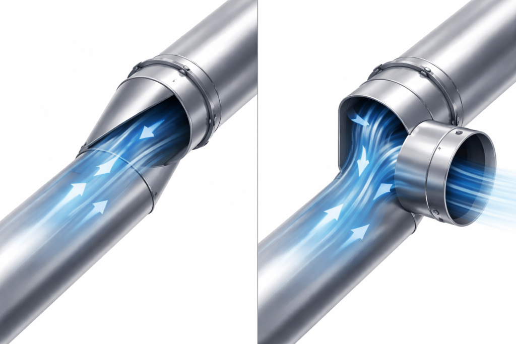
A frequent field error is the use of standard “T-junctions” in LEV ductwork. In industrial extraction, every branch must enter the main duct at an angle of 30 to 45 degrees to minimize turbulence and pressure loss. Using a 90-degree “T” creates a dead zone where dust accumulates, eventually choking the system and increasing the risk of a flash fire if the dust is combustible.
Filtration and Discharge: The Final Stage of LEV
The captured air cannot simply be exhausted outside without treatment. Depending on the contaminant, the system must integrate a baghouse filter, a cyclone separator, or a chemical scrubber. The choice of filtration impacts the Total Static Pressure of the system; as filters get “loaded” with dust, the resistance increases, and the delivered CFM will drop unless the fan is controlled by a Variable Frequency Drive (VFD) that compensates for this pressure spike.
In the local market, compliance with occupational health and safety (OHS/İSG) regulations is a major driver for LEV adoption. For companies dealing with hazardous substances, a “certified” LEV system is a legal requirement. This includes ensuring that the “Clean Air” discharge is positioned away from building intakes to prevent the re-entry of contaminants.
Engineering Checklist for LEV Systems:
- Source Proximity: Confirm the hood is placed as close to the contaminant source as physically possible.
- Capture Velocity Verification: Measure air speed at the furthest point of contaminant generation to ensure it meets ACGIH or ISO standards.
- Transport Velocity Check: Verify that duct air speeds are high enough to prevent material fallout in horizontal runs.
- Static Pressure Port Installation: Ensure there are test ports before and after the filter for easy monitoring of filter health.
- Fan Rotation: Verify the centrifugal fan is rotating in the correct direction (a common site error that still allows some airflow but at drastically reduced efficiency).
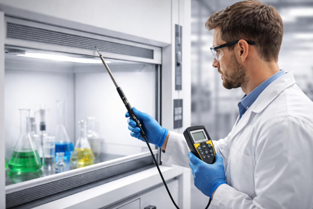
Designing an LEV system requires more than just “pulling air”; it requires a deep understanding of the material being handled and the physics of airflow at the hood. For industrial facilities looking to upgrade their extraction systems or seeking a technical get a quote for a new installation, our engineering team provides end-to-end support from AutoCAD modeling to site commissioning. For direct inquiries regarding specialized fan selection or duct design, please reach out via our contact page.