

In the landscape of mechanical installation and industrial climate control, CFM (Cubic Feet per Minute) is the fundamental metric that bridges theoretical design and operational reality. Often described as the “heartbeat” of a ventilation system, CFM quantifies the volume of air moving through a space or a duct every minute. For project managers, technical offices, and facility owners, mastering CFM is not just about comfort; it is about ensuring energy efficiency, meeting health regulations, and protecting the longevity of expensive mechanical equipment. At AVENT PROJE, we treat every CFM calculation as a commitment to precision, ensuring that the services deliver the exact environmental conditions required by your specific project.
The Physics of Airflow: Volume, Velocity, and Area Dynamics
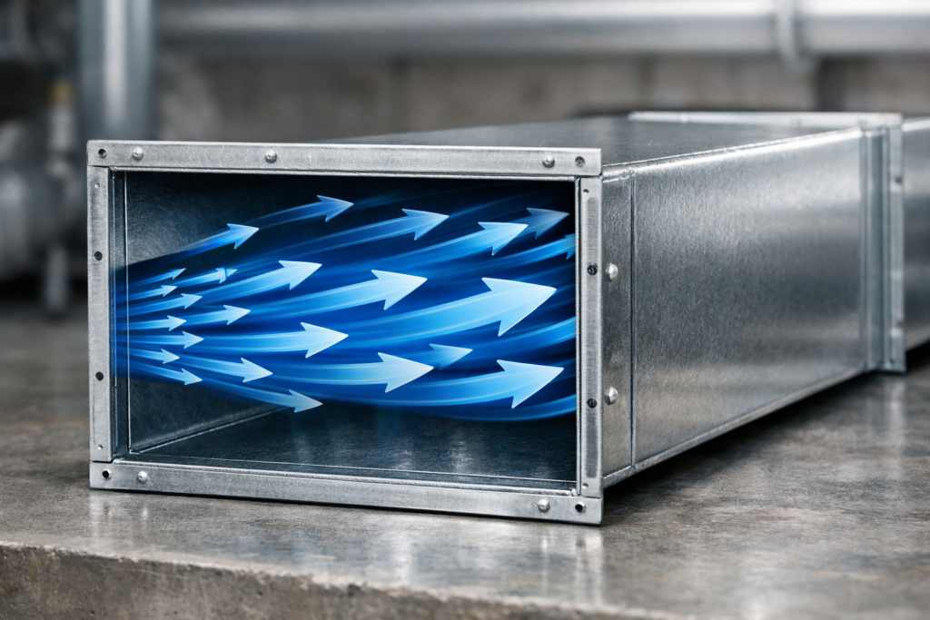
The measurement of CFM is fundamentally tied to the geometry of the delivery system and the speed of the air. In the engineering world, the most critical relationship to understand is the airflow formula: CFM = Velocity (FPM) x Area (sq. ft.). This equation dictates that for a fixed amount of air, if you decrease the duct size (Area), the velocity (FPM) must increase.
From an engineering perspective, selecting the right duct size is a delicate balance between space constraints and acoustics. If the velocity is too high—often exceeding 1,500 FPM in commercial branch ducts—the friction results in excessive noise and vibration, which can be detrimental in office or hospital environments. Conversely, if the velocity is too low, the air may not have enough momentum to reach the farthest diffusers, leading to stagnant zones.
In a typical field scenario involving a large-scale commercial kitchen, we often observe systems where the exhaust hoods fail to capture smoke effectively. The issue is rarely the fan’s maximum capacity, but rather an improperly sized duct that creates a “choke point.” By recalculating the area-to-velocity ratio, technical offices can optimize the system to ensure the hood maintains the required “capture velocity” without increasing the energy bill.

Thermal Load Calculations and the Science of Heat Transfer
CFM is the primary vehicle for moving thermal energy. To maintain a constant temperature in a room, the HVAC system must deliver a volume of air that can offset the heat gained from equipment, sunlight, and occupants. The standard engineering formula for sensible cooling is: CFM = Sensible Heat (BTU/hr) / (1.08 x Delta T). Here, Delta T represents the temperature difference between the supply air and the room air.
While many contractors rely on “rules of thumb”—such as 400 CFM per ton of cooling—this approach often fails in specialized environments like data centers or pharmaceutical labs. In these high-load scenarios, our about us highlighted engineering vision demands a more rigorous psychrometric analysis. A data center, for example, produces immense sensible heat but very little moisture (latent heat). If the CFM is not precisely tuned to this ratio, the system may over-cool the space while failing to manage the concentrated heat spikes near the server racks.
A common scenario we encounter involves a “one-size-fits-all” approach to office layouts. When a meeting room designed for 5 people is suddenly used for 20, the original CFM allocation becomes insufficient. This results in an immediate spike in Carbon Dioxide (CO2) levels and a drop in occupant productivity. Modern mechanical projelendirme solves this by utilizing Variable Air Volume (VAV) systems that adjust the CFM in real-time based on sensor data.
Static Pressure: Navigating the Resistance to Airflow
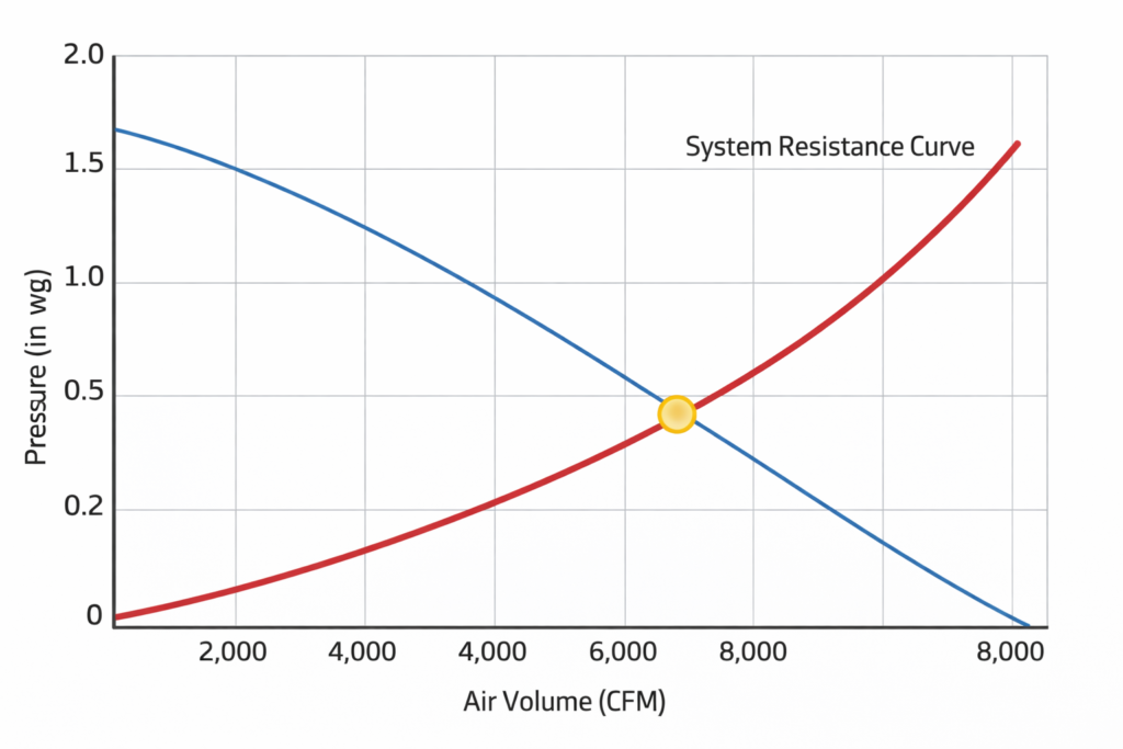
Air does not move through a building for free; it must overcome resistance known as static pressure. Every component in the system—from the cooling coil and high-efficiency filters to the dampers and every single elbow in the ductwork—pushes back against the fan. This relationship is governed by the “Fan Laws,” which state that if you want to double the CFM, you must quadruple the pressure capability, which in turn requires an eightfold increase in power consumption.
This cubic relationship between CFM and power is why pressure drop management is the hallmark of professional engineering. In our technical blog section, we often discuss the “System Effect,” where poor installation practices (like placing a sharp bend immediately after a fan outlet) create unexpected turbulence. This turbulence increases static pressure far beyond the manufacturer’s datasheet, causing the actual delivered CFM to plummet.
A frequent field error occurs when facility managers upgrade to higher-rated MERV filters (e.g., switching from MERV 8 to MERV 13) to improve air quality. While the filtration improves, the denser material increases the pressure drop. If the fan was already operating near its limit, the delivered CFM will drop significantly, potentially causing the evaporator coil to freeze or the motors to overheat due to the lack of airflow.
Strategic Distribution and System Balancing Protocols
The final stage of any HVAC project is Ensuring that the calculated CFM actually reaches the diffusers. This process, known as Testing, Adjusting, and Balancing (TAB), is what transforms a collection of ducts and fans into a functional system. Without a professional TAB report, a building is likely to have “hot” and “cold” spots, regardless of how powerful the central unit is.
In large-scale industrial projects, the challenge is often the “throw” and “spread” of the air. If a diffuser is assigned 500 CFM but the duct velocity is too low, the air will simply “dump” directly beneath the vent rather than mixing with the room air. This leads to poor thermal stratification. Conversely, undersized flexible ducts—often squeezed through tight structural gaps during construction—can lose up to 50% of their rated CFM due to friction and kinking.
Engineering Commissioning Checklist for CFM:
- Total Airflow Verification: Use a pitot-tube traverse in the main supply duct to confirm the AHU is delivering the design total CFM.
- External Static Pressure (ESP) Check: Measure the pressure across the fan to ensure it matches the fan curve.
- Diffuser Balancing: Use a flow hood (balometer) at every outlet to ensure +/- 10% accuracy from the design value.
- Damper Locking: Ensure all volume control dampers (VCDs) are locked in their balanced positions to prevent future drifting.
- Motor Amperage: Verify that the fan motor is not “over-amping” while trying to maintain high CFM against high resistance.
For projects where precision is non-negotiable, obtaining a technical get a quote for a comprehensive airflow audit can save thousands in operational costs. A well-balanced system doesn’t just feel better; it lasts longer and consumes significantly less energy. If you are experiencing airflow issues or planning a new mechanical installation, our technical office is ready to provide the engineering expertise needed to optimize your system. Please reach out to us through our iletisim page for a detailed consultation.